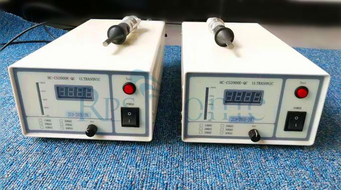
High Frequency Power Supply Circuit PCB High Efficiency Strong Output
Description| Frequency: | 15Khz~60khz | Power: | 2500W In Max |
|---|---|---|---|
| Excitement: | Separate Excitation | Generator: | Digital Generator |
| Operate: | Rotary Button | Frequency Range: | +-1000hz |
| High Light: | high power ultrasonic generator,ultrasonic wave generator | ||
high frequency ultrasonic welding generator circuit diagram PCB for welding
Parameter:
| Item | Parameter |
| Power | 3000W In max |
| Frequency range | ±1khz |
| Operating temperature | ≤65℃ |
| Frequency | 20Khz~60khz |
| Amplitude adjust | 10%~90% |
| Voltage | 110V/220V |
| Circuit | Digital,separate excitation |
Why RPS-SONIC Generator:
1. Each power will be tested by Specifytransducer .
2. All generatorwith one year warranty.
3. Specialized in high power ultrasonicfor more than ten years
4. Every generatorwith 24hours old testing before shipment.
5. Good packing, no packing problem during the 10 years exporting business.
6. Every customer will get purchase records and there are certain rewards after accumulation
Advantages:
1. High reliability,2. High efficiency, abandoning low-efficiency power transformers3. Transducer protectionextend the use of the transducer life;4. Strong output,accurate resonance, large output power5. Resonant frequency tracking6. Amplitude adjustment and output power continuously adjustable from 10% to 90%;7. Miniaturization and light weight120*120*380mm in size and 2.5kgs in weight.
An ultrasonic welding generator is a device for generating and supplying ultrasonic energy to an ultrasonic transducer. The purpose is to convert our city power (220V or 380V, 50Hz or 60Hz) into a high-frequency AC signal that can be matched with an ultrasonic transducer. This signal can be a sinusoidal signal or a pulse signal.The ultrasonic power supply is divided into aself-excitation power supplyand aseparate-excitation power supplyaccording to the design.The self-excited circuit has no signal source. It integrates the oscillation, power amplifier, output transformer and transducer into a closed loop. The loop meets the amplitude and phase feedback conditions to form an oscillator with power amplification. And resonate at the mechanical resonance frequency of the transducer. Generally applied to small devices with a small number of ultrasonic transducers; however, for a large number of ultrasonic transducers, it is impossible to debug to achieve resonance effects. Therefore, the ultrasonic power supply of industrial ultrasonic cleaning equipment mostly uses a separate excitation method. The structure of the separate-excitation power supply mainly includes two parts, the former stage is an oscillator, and the latter stage is an amplifier. Generally coupled through an output transformer, ultrasonic energy is applied to the transducer. The separate-excitation circuit consists of two parts, the signal source part and the signal amplification part.The signal source part uses the CPU as the core of the signal generation and control part. Generally, it is driven by 12-15V voltage to generate a square wave signal and supply it to the signal amplification circuit. The additional functions such as timing control and adjustment of the ultrasonic power supply can control the signal of the signal source The output mode is completed, and low voltage control is adopted, and the safety and reliability will definitely be high.The signal amplification part is to amplify the signal generated by the signal source and output it to the ultrasonic transducer. The difference in the output circuit and voltage of the ultrasonic power supply of different circuits is an important reason for the high and low propagation efficiency. The output voltage is low, and the generator consumes large amount of power naturally. At the same time, the vibrator is easy to generate heat, and the induced electric field is strong. Properly adjusting the circuit and increasing the output voltage to the ultrasonic transducer may achieve good results.In digital electronic equipment, waveform generation circuit has always been a very important circuit. Among various waveforms, although a sine wave is not the most commonly used waveform, it is not easy to produce an accurate and stable sine wave. The traditional sine wave generating circuit is generally implemented by analog circuits, which is neither accurate nor stable, and is bulky. With the digital development of the circuit system, digital frequency synthesis is directly applied.Using a DSP chip and D / A converter, and using direct digital frequency synthesis technology, a sinusoidal signal generator with controllable frequency and phase is designed and implemented. The digital system controls its output power, amplitude and energy by its frequency setting, tracking compensation, amplitude setting, amplified matching output, and signal detection and analysis. Moreover, the ultrasonic computer-controlled welding system is provided with various application modes such as time, energy, distance size, depth size, etc. to achieve different welding requirements. The system has the characteristics of high accuracy, intuitive display, high degree of intelligence, flexible control, better performance, better reliability and stability, ease of use and high cost performance.The traditional analog circuit is composed of its excited or self-excited discrete components, which are amplified and matched to the transducer to form a closed loop circuit. After simple time control to achieve ultrasonic welding. However, it is impossible to preset its frequency, amplitude, and energy control, and only simple time welding can be achieved. Some domestic manufacturers use computer touch screens for control. On the surface, the equipment level is improved. In fact, even the time is not accurate enough to meet some more Demanding product welding.
